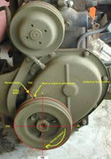
Post by Scoutpilot on Jul 26, 2015 7:03:41 GMT -5
Tune-up your L 134
What constitutes a Tune-up?
A tune-up can be as simple as plugs, points and condenser or it can be a full-blown, check/test/service everything, replace or repair everything from the front bumper to the rear bumper. What I am going to describe, in a limited manner, with emphasis on the L 134 "Go Devil" and Hurricane motors and their appliances and necessaries, is what should be done on an annual basis and this would include an oil and filter change with a radiator flush and fill. The Service Manual calls for twice a year service on your Jeep. I can see this if yours is a Daily Driver. But, if you are like most, the old critter hibernates through the winter. Once a year should be sufficient. I’m writing it this way for the simple reason that EVERY system works with EVERY other system and if one is out of kilter, the entire Jeep is out of kilter. Caveat; NAPA changes part numbers from time to time but the good old grey-haired guys behind the counter can still cross reference and get you what you need. Have all of your needed parts and supplies on hand and this job (sorry Murphy) shouldn’t take very long.Tools.
You will need a Vacuum/Fuel Pressure Gauge
Dwell/Tachometer
Volt/Ohm Meter
Battery Hydrometer
Anti-freeze Tester
Nice to have:
Laser Thermometer
Remote Starter Switch
Appropriate wrenches, screwdrivers, measuring gauges and such.
Everything hinges on a good Battery.
CAUTION. You are dealing with a tar/rubber/plastic box full of Sulfuric Acid! Wear gloves and eye protection. Keep a box of Baking Soda and a water hose handy for spills.
• Never work on a battery with a lit cigarette in your mouth. Batteries are filled with sulfuric acid that generates hydrogen gas. If you get acid deposits on your skin or clothes, wash them off with water immediately.
• Disconnect the battery whenever you work on it.
• Always remove the negative cable from the battery if you plan to work on wiring under the hood. This prevents you from possibly damaging electrical components or receiving a shock.
• When removing and replacing both battery cables, always remove the negative cable first and replace it last. If you attempt to remove the positive clamp first and your wrench slips and touches something metal, your wrench can fuse to the part like an arc welder.
• Tie the cables back while you work on the battery. Don’t allow anything made of metal to connect the terminal posts; this can damage the battery.
With the caps on tight, sprinkle Baking Soda to cover the top of the battery. Let it sit for a minute. Rinse off with water. This will neutralize any acid on the cover and terminals as well as flushing the entire battery area free of acid.
Remove the cable ends from the terminals. Brush-clean the terminals and connectors. Inspect the cables and be sure they are tight and clean in the connectors. Leave them off for now.
Be it 6 or 12 volt, it should be fully charged. For information on how to test a battery, check out the following links.
If you have a six volt system, your battery and starter cables need to be 00 ga to no smaller than 2 ga cable. Downstream wiring needs to be appropriately sized as well. You can look to this link for information.
Inspect ALL the frame/motor/tub grounds for clean bright connections. Remove any corrosion.
Generator/Alternator.
The drive belt should be the correct size for the pulleys. Check the belt tension. 1/4 inch of deflection by hand, min/max. Check the belt for fraying and wear. Check the pulley for wobble. Wiring should be clean, solid connections. If your generator has oil ports front and rear, place a couple of drops of used motor oil in each. You can use oil drained from the pan for this.Voltage Regulator.
Properly adjusted with clean, solid connections and base grounded.Ignition Switch.
I don’t care what you use, key start, key switch and floor button, what have you. Inspect for clean, solid connections and proper action of each switch.Starter Solenoid.
If you have one in line, inspect for heat damage and condition of the connections.Have a ballast resistor in line?
CAUTION. If you are running an electronic ignition module your wiring setup will be slightly different from standard. Read your installation instructions carefully.A ballast resistor limits the amount of current flowing in an electrical circuit. The most common automotive use for a ballast resistor is to regulate the voltage to the ignition system by being inserted in series in the primary circuit between the ignition switch and the positive terminal of the ignition coil. It is usually located in the open near the ignition coil so that it can dissipate its heat into the air. An ignition system with breaker points will suffer due to reduced point life if the ballast resistor is removed, as higher amperage can damage the surface of the points causing failure. Additionally, if the ignition is left in the run position and the points happen to be open-or worse, barely open-electrical arcs can cause raised spots on the points resulting in a change in dwell timing or an engine that won't run at all. Twelve volt ignition coils may or may not need a ballast resistor. Be sure you know which type of coil you have. Ballast Resistor requirements should be printed on the coil. Inspect it’s connections and look for heat damage. When in doubt, Do a resistance test with your Ohm Meter. If it doesn’t pass, replace it with new.
Starter.
All connections need to be clean and tight. If you want, you can remove it and inspect the Bendix and bushings.Coil.
Six or 12 volt? Resistor required? Look for heat damage, oil leakage and inspect the connections. Physically check the wire from the ballast resistor or ignition switch to the positive side of the coil.Distributor Cap (Echlin Al 70).
Inspect contact condition (inside and out), look for carbon trails and cracks.Distributor.
Standard for the L-134 and early F-134 is the Autolite IAD4008. Physically check the wire from the coil negative side. If your distributor has an oil port, pull the cap straight out and place a couple of drops of motor oil in it. You can use oil drained from the pan for this. Inspect distributor shaft for play in the bushing by gently rocking it side to side. Inspect all wiring connections for proper isolation against shorting out. Check the advance springs by grasping the shaft top and rotate the shaft ccw to its stop (not far at all) and release. If it doesn’t snap back, springs may be stretched or spring posts may be bent and/or worn.Rotor (Echlin AL 69)
Inspect the contact for excessive wear.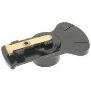
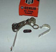
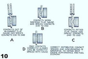
Points (Echlin CS 725 A).
Dwell 42º, +/- 1º.
Condenser (Echlin Al 116).
Be certain the wire will not be in direct contact with any sharp edge, or be pinched, causing wear in the insulation and create a short circuit.Spark plugs (Champion J-8-C, Autolite 295)
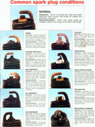
Inspect for condition. Clean using a spark plug cleaner.
Clean, re-gap to .030”, check with a feeler gauge and re-install if in good condition. But if you have to replace one, replace all.
Compression Check.
Since you have the plugs out, now would be a good time to perform a compression check. Disconnect the coil high tension lead and reconnect the battery. Parking/Emergency brake applied with the transmission in neutral. Throttle held full open. Dry Test: Start anywhere. 100+ psi, with all cylinders being within 10 psi of each other is very good. Wet Test: Pour a tablespoon or two of motor oil into the cylinder via the spark plug hole. Again, start anywhere. 100+ psi, with all cylinders being within 10 psi of each other is very good. A 10+% differential between any two indicates leakage.Plug wires.
If you’re not running copper core, you should be. Inspect for cracks and wear in the sheathing. Inspect the connectors for condition. If you have to replace one, replace all, including the coil wire. Correct firing order is Counter Clockwise 1 - 3 - 4 - 2.Fuel filter.
If it is a replaceable paper element or a cheap plastic throw-away, do just that and replace it. If you have a ceramic element, clean it with carb cleaner, inspect the gasket and spring. If both are good, reinstall and move on. Air filter/cleaner.
Oil Bath? Remove it, disassemble it, clean it, refill it to the proper level with 30W motor oil, and re-install it. Paper? You can try and blow it clean with compressed air but know that even with that effort you probably won’t get it clean enough to be as efficient as when it was new. Buy a new one. Check the tubes for condition and tightness of connections. Replace as necessary.PCV Valve.
For the permanent PCV valve, remove the tube and the valve. Dis-assemble the valve, clean and reassemble in the exact order and orientation. If you don’t reassemble it correctly, it will not work correctly and your performance will suffer drastically and immediately. Reinstall on intake.Heat Riser.
Inspect for smooth operation of the rod. Inspect the bimetal spring and contact arm for condition and alignment. The heat riser allows for a fast, efficient warm-up.Credit to Professor Ryan Murdock for this video.
Exhaust.
Inspect the manifold, collector, pipe, muffler and tail pipe for rust or damage.Fuel Pump.
Inspect the pump for fuel and oil leaks. If it is a serviceable unit, remove the bowl and clean it. Inspect the gasket. Replace as required. Be sure the bail is tight when re-assembling.Valve Adjustment.
Tools required:
Two 1/2" open end wrenches and these specialty tools:
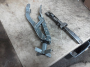
Left - Valve Spring Compression Tool.
Right - Keeper Removal/Installation Tool
Magnetic Part Retrieval Tool
This should be done annually. Use the “Rule of Nine”. You might want to watch the following video;Tools required:
Two 1/2" open end wrenches and these specialty tools:

Left - Valve Spring Compression Tool.
Right - Keeper Removal/Installation Tool
Magnetic Part Retrieval Tool
I haven’t tried this method, but it sounds solid to me.
HOW TO VERY ACCURATELY ADJUST L/F134 VALVE TAPPETS QUICKLY WITHOUT USING FEELER GAUGES
By John GIBBINS 14th July 2015
There are many ways to adjust tappets but this is the simplest way that the novice [hobbyist] or experienced mechanic can do things in minutes with absolutely no confusion. As well on older vehicles there will be wear on the valve stem & tappet that is not conducive to being accurately set with feeler gauges. Adjusting without feelers avoids this pitfall.
So just 1 flat of the hexagonal head is 0.042"/6 = 0.007" & 2 flats is 0.042”/3 or 0.014”. If you want 0.016” just a tad more.
Frankly I have always adjusted L134 valves to 0.014” cold & never had a burned exhaust valve or any other deleterious consequences ….fuels & oils Knowing the L/F 134 engine tappet adjuster screw has 24 threads per inch 1 complete 3600 turn of the tappet adjuster hexagonal head [6 flats] is [1"/24] or 0.042". are VERY different now from when the clearances were altered to 0.016" from the head casting marks 0.014".
Adjusting valves is quite easy whether a mechanic or not...This is the no-feeler method that ensures wear to the cam follower screw head is eliminated from the measuring equation [so is the ticking noise, usually].
An aside here is....One reason we should ALWAYS replace cam followers in the same position on the same cam lobe if they have been removed for any reason is that cam & follower patterns mismatched can cause non-removable ticking noises & accelerated wear.
FIRST....Get 1 at TDC compression with marks in the window or finger over the plug hole or loosely fitted tissue blowing out [all spark plugs are removed] & someone turning the crank handle.
As you are adjusting valves the side cover will be off another check that is easy to establish 1 is @ TDC compression is number 4 valves will be on the rock i.e. exhaust valve is closing & the inlet is opening or alternatively the distributor rotor position will be to number 1 plug lead.
NOW....When @ TDC compression with chalk mark the center left side of the crankshaft belt pulley parallel to the ground.
1. Adjust both number 1 valves by screwing the adjuster till there is just no play then unscrewing/loosening the adjuster only 2 flats of the hex head. That will give you exactly 0.014" gap
2. Turn engine with crank 180 degrees then the chalk mark will be on the right side parallel to the ground. Now adjust both no 3 tappets, exactly as done in 1.
3. Another 180 degrees so the mark is now left parallel with the ground then adjust no 4 tappets, as done with valves 1&3
4. Only 2 is left so when the mark is right parallel to the ground adjust both no 2 tappets, like with valves 1,3 & 4.
All done in 5-10 minutes
Inspect the radiator.
Leaks in the joints. Weeping from the fins. Use a "Radiator Comb" to gently, very gently, straighten the fins. Coolant/Antifreeze, radiator with baffle in top? 1/2 way up baffle. No baffle? only just covering the tube ends. Flush and change annually. The upper and lower hoses should be firm to the touch. Squeeze them, and if very soft, replace them.Water pump.
Check for cracks and leaks. The first place a worn pump will leak is from the weep hole in the bottom. Replace or rebuild as suits you.
Thermostat.
Thermostats do wear out with age and heating/cooling cycles. The choice of opening temperature should be governed by your geographical location and predominant climatological conditions.
Motor Oil.
I hope you are using an oil high in ZDDP. Look to the following link for the proper viscosity for your region. The filter is a NAPA 1010. Five quarts with a filter change is standard.Transmission Fluid.
GL-1 to the bottom of the filler port. Inspect for leaks.Transfer Case Oil.
GL-1 to the bottom of the filler port. Inspect for leaks.Differentials.
(80-90W) to the bottom of the filler port. Inspect for leaks.Chassis Lubrication.
Lube the chassis, spring pivots, steering and propeller shafts. See your Owner’s Manual for the Lubrication Chart.Brake Fluid.
Check brake fluid level. This is normally DOT 3 or 4. But as has been noted by our esteemed colleague Leemn, it can and will break down after some years of use and allow water to condense in the lines. You can step up to Silicone (DOT 5), which is great for Jeeps that see limited use, and adds years to the life of the brake system, but you must first completely flush the brake system as 5 does not mix with 3 or 4. Inspect the lines and connections for leaks.Tires.
Rotate tires (Optional). But don’t forget your spare, if you have one. It should be rotated into the mix. Check tire pressures cold. Know the manufacturer's recommended cold pressures. Inspect for excessive wear which may indicate faulty alignment or excessive shock absorber wear.Lights.
Connect the battery cables. Check all of your lights. Have someone press the brake pedal to check the brake light(s).All right. Before you start the motor.
All of the following items should be set up within easy reach on the carburetor side of the motor and visible from either side of the motor.Hopefully, you’ve plumbed the intake manifold for a vacuum connection. If you have a vacuum-powered wiper, you should already have one. This port is where you hook up the Vacuum gauge.
Connect your Dwell/Tachometer Ground lead to the negative (-) terminal of the battery and the Positive lead to either the terminal on the exterior of the distributor or the out-to-dizzy terminal on the coil.
Connect the leads for your timing light, if you use one.
If you have the luxury of a remote starter switch, so much the better, hook it up. Having someone to assist you at this point would be very helpful.
Chock a wheel, set the parking brake, and take the transmission out of gear.
A quick double-check to be sure all is set, tight, and ready.
Fire it up!
Apply choke as required. Pump the pedal as required and start it. Check the oil pressure for a satisfactory reading. Let it warm up to at or near operating temperature, a minimum of 140º. Open the choke fully. Rev it up a couple of times and let it settle. Your vacuum gauge should be reading between 15 and 21 inches Hg. The higher the better and the needle should be relatively steady. Your tachometer should be indicating between 600 and 700 RPM at idle. Your Dwell angle should be 41º to 42º. Remember, if you are using a Dwell/Tach with only 6 and 8-cylinder scales, look to the eight-cylinder scale and double the reading for the correct number. Check the timing with the timing light aimed at the open port (You will have to move the guard out of the way) on the bell housing splash shield. It should be indicating 5º BTDC. In the case of this flywheel, you’re looking for the ‘IGN’ mark.
After all these checks, slowly pull the throttle open and check for any stumble or hesitation.
Satisfied?
If so, grab your assistant(s) and go for a ride.If not, shut it down and we’ll move on to troubleshooting.

